

-
大功率、高精度、低纹波的稳定直流电源不仅是重离子加速器的重要子系统,而且在其他大科学装置中的应用越来越广泛[1-3]。磁铁电源系统作为重离子加速器系统的重要组成部分,大量非线性器件如各类磁铁元件、注入引出元件、诊断元件等应用于磁铁电源中,使重离子加速器磁铁电源输出的电流中产生了大量纹波[4-7],纹波的存在导致磁铁电源输出的电流无法满足加速器的需求,使得加速器整个运行过程存在很大的安全隐患,严重地影响了加速器的束流品质[8-11]。中国科学院近代物理研究所主要开展重离子物理基础等研究,对磁场稳定度要求极为严格,磁场的长期稳定,要求加速器磁铁电源输出电流必须长期稳定。在输出稳定的磁场束流的场合下,要求磁铁电源输出电流纹波极低,产生精确控制粒子运动的磁场,一般要求电源的纹波系数为
${10^{{{ - }}4}} \sim {10^{{{ - }}5}}$ [8]。为降低加速器磁铁电源输出的纹波电流,常规方法是在稳定直流电源系统中应用电压型有源电力滤波器(Voltage Source Shunt Active Power Filter,VSAPF)。但是电压型有源电力滤波器的性能受磁性负载的影响较大,抑制效果并不是十分理想。文献[12]用VSAPF降低直流磁铁电源纹波,通过检测负载电压实现对纹波电流的控制,该过程存在计算误差,无法达到加速器电源系统对电流纹波系数的要求;文献[13]提出了采用直流有源滤波器的检测纹波电压控制方法,该方法的优点是对传感器和电路元件精度要求不高,但纹波电压和纹波电流之间的转换关系增加了控制器的复杂度,导致系统响应延时;文献[14]采用串联型有源电力滤波器对输出的电压和电流纹波进行抑制,但串联型有源电力滤波器因保护电路复杂、设备损耗较大在加速器等大科学装置中而被限制。
目前,对纹波电流抑制的研究主要集中在VSAPF,本文提出电流型有源电力滤波器(Current Source Shunt Active Power Filter,CSAPF)[15]替代VSAPF对电流纹波抑制,并对VSAPF和CSAPF的纹波抑制能力进行比较。首先,讨论了VSAPF和CSAPF的主电路拓扑结构;其次,研究了基于纹波电流反馈的控制系统;最后,比较了两种滤波器在加速器电源系统的稳定性与可靠性。
-
直流有源电力滤波器能够消除磁铁电源输出电流中的纹波成分,使得磁铁电源输出电流不受系统所带负载的影响只输出直流,消除纹波成分。直流有源电力滤波器的基本原理为:首先利用系统资源检测需要补偿的纹波信号作为指令信号,再通过控制主电路的逆变器产生实时补偿电流,进而对电路中产生的纹波电流进行补偿。有源电力滤波器的基本数学模型为
式中
${i_{\rm{s}}}$ 、${{{i}}_{\rm{L}}}$ 、${{{i}}_{\rm{f}}}$ 分别表示磁铁电源输出电流、负载电流、滤波器发出的补偿电流;${{{i}}_{\rm{d}}}$ 、${{{i}}_{\rm{h}}}$ 分别为负载电流中的直流分量和纹波分量。图1中
${{{u}}_{\rm{dc}}}$ 表示直流侧储能元件电容电压;${{{i}}_{\rm{dc}}}$ 为直流侧储能元件电感提供的直流电流。为分析电流型有源电力滤波器的工作机理,根据图1(a)中CSAPF中各器件的小信号模型电路建立数学模型,单相CSAPF的等效电路图如图2所示,其中${{{u}}_{\rm{s}}}$ 为前级系统电压,${{{i}}_{\rm{s}}}$ 为前级系统电流,R表示线路等效电阻,L、C分别为滤波电感和滤波电容,${{{i}}_{\rm{L}}}$ 是负载电流,${{{i}}_{\rm{f}}}$ 表示电流型有源电力滤波器发出的补偿电流。下面将从时域和频域分别对单相电流型有源电力滤波器建模分析。
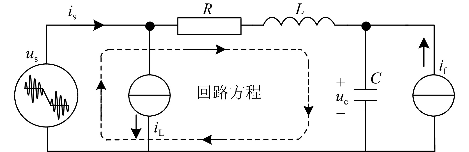
根据图2中CSAPF的等效电路,得到状态方程如下:
为了便于CSAPF数学模型的建立,假设开关管IGBT为理想的开关器件,其开关函数定义为
根据单相CSAPF的工作原理和式(4),得到其系统电压和电流的关系为
将式(6)代入式(4),进行拉普拉斯变换,得到频域下单相电流型有源电力滤波器的状态方程为
根据式(7),给出CSAPF工作原理图,如图3所示。对于该系统,
${{{i}}_{\rm{f}}}$ 和${{{i}}_{\rm{L}}}$ 为两个被控量,$ R{\text{、}}{L}_{\rm{f}}{\text{、}}{{C}}_{\rm{f}}{\text{、}}{{L}}_{\rm{dc}}$ 为已知量,根据式(7)状态方程,采用合理的控制策略通过对开关函数${{{S}}_{{a}}}$ 和${{{S}}_{{b}}}$ 的控制,进而实现对${{{i}}_{\rm{f}}}$ 和${{{i}}_{\rm{L}}}$ 的控制,使得单相电流型有源电力滤波器能够抑制谐波电流。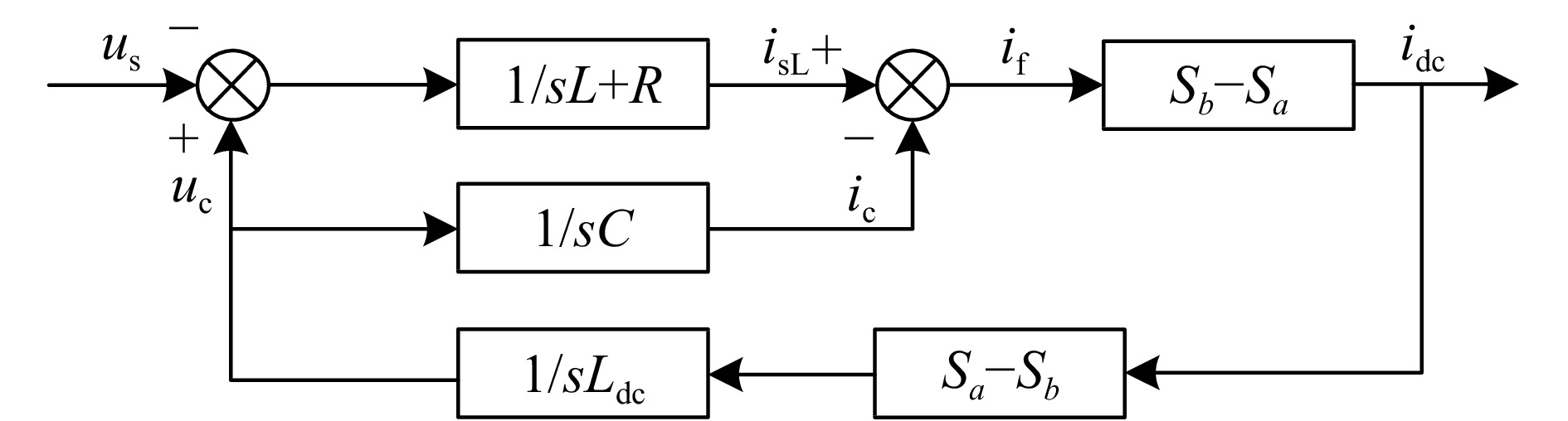
根据CSAPF工作原理及主电路拓扑结构,可以得到CSAPF具体的工作模态如图4所示。
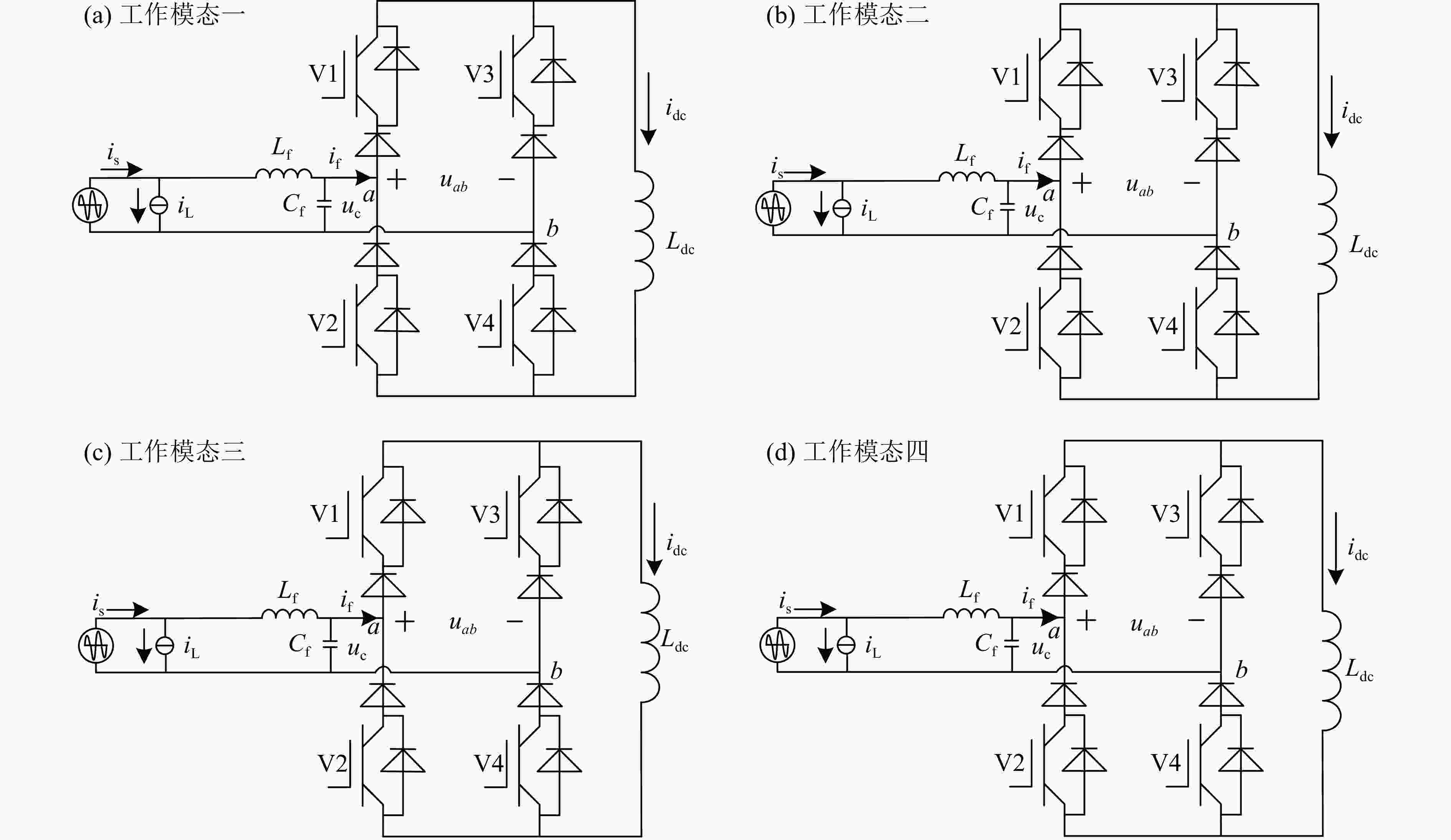
因直流侧储能元件为大电感,需要保证直流侧电感中时刻有电流流过,为维持
${i_{\rm{dc}}}$ 的稳定,要求CSAPF主电路中IGBT按照不同的导通顺序工作,具体工作模态如图4所示。(1)工作模态一,
${{{S}}_1}$ 和${{{S}}_4}$ 导通,此时电路方程为当补偿电流
${i_{\rm{f}}}$ 为正时,V1和V4同时导通,磁铁电源前级侧吸收能量,${L_{\rm{dc}}}$ 输出能量,工作在能量反馈模态下,${i_{\rm{f}}}$ 减小,滤波电容${C_{\rm{f}}}$ 存储能量;当${i_{\rm{f}}}$ 为负时,V1和V4旁侧二极管导通,磁铁电源前级侧输出能量,直流侧吸收能量,此时工作在整流模态下,并随着${i_{\rm{f}}}$ 增大,${C_{\rm{f}}}$ 开始释放能量。(2)工作模态二,
${{{S}}_2}$ 和${{{S}}_3}$ 导通,此时电路方程为当补偿电流
${i_{\rm{f}}}$ 为正时,V2和V3旁侧二极管D2和D3导通,前级侧滤波元件${L_{\rm{f}}}$ 、${C_{\rm{f}}}$ 、直流侧${L_{\rm{dc}}}$ 均吸收能量,此时${i_{\rm{f}}}$ 减小,${C_{\rm{f}}}$ 释放能量;当${i_{\rm{f}}}$ 为负时,V2和V3导通,${L_{\rm{f}}}$ 、${C_{\rm{f}}}$ 、${L_{\rm{dc}}}$ 均输出能量,此时${i_{\rm{f}}}$ 增大,${C_{\rm{f}}}$ 存储能量。(3)工作模态三,
${{{S}}_1}$ 和${{{S}}_3}$ 导通,此时电路方程为当
${i_{\rm{f}}}$ 为正时,V3旁侧二极管D3和V1导通,${i_{\rm{f}}}$ 减小,${C_{\rm{f}}}$ 释放能量;当${i_{\rm{f}}}$ 为负时,V1旁侧二极管D1和V3导通,${i_{\rm{f}}}$ 增大,${C_{\rm{f}}}$ 存储能量。此时前级电流与开关器件构成闭合回路,直流侧电流保持稳定。(4)工作模态四,
${{{S}}_2}$ 和${{{S}}_4}$ 导通,此时电路方程为当
${i_{\rm{f}}}$ 为正时,V2旁侧二极管D2和V4导通,${i_{\rm{f}}}$ 减小,${C_{\rm{f}}}$ 释放能量;当${i_{\rm{f}}}$ 为负时,V4旁侧二极管D4和V2导通,${i_{\rm{f}}}$ 增大,${C_{\rm{f}}}$ 存储能量。此时前级电流与开关器件构成闭合回路,直流侧电流保持稳定。通过对CSAPF四种工作模态的分析,可以利用所提控制策略对开关器件的导通与关断进行控制,以便保持直流侧储能元件电感上流过电流的稳定,进而控制CSAPF产生补偿电流。根据其电路特性与数学模型,对系统的稳定性进行分析。
-
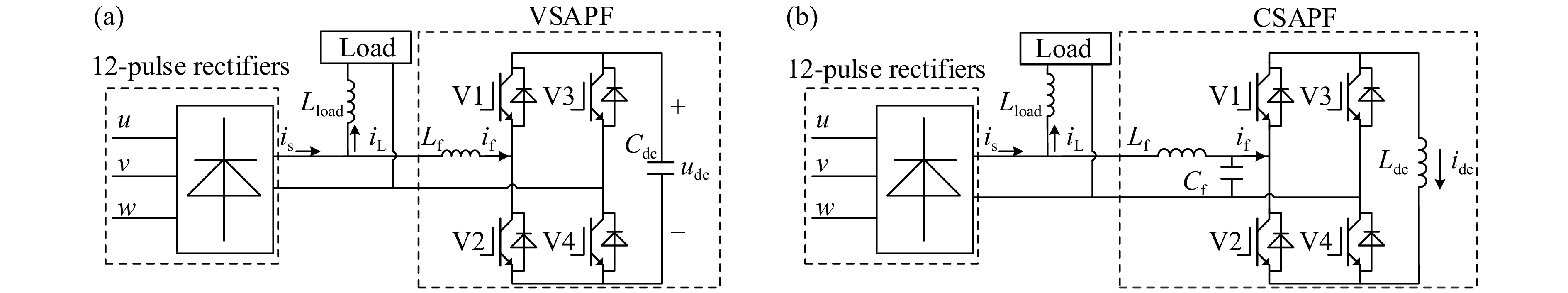
如图1(a)所示,电压型并联有源电力滤波器应用在磁铁电源输出电流纹波抑制系统中的拓扑结构,V1-V4构成的H桥逆变器作为VSAPF的主电路。为消除电力电子设备自身产生的谐波,在12脉冲整流电路与VSAPF之间接入一阶滤波器;为保持VSAPF正常运行,直流侧储能电容器
${{{C}}_{\rm{dc}}}$ 必须保持其直流母线电压${{{u}}_{\rm{dc}}}$ 大于线路电压的峰值,以准确控制VSAPF产生的补偿电流,进而吸收磁铁电源输出的电流纹波。 -
如图1(b)所示,H桥逆变器(V1-V4)构成CSAPF主电路,用于磁铁电源输出电流纹波抑制。CSAPF直流侧储能元件电感
${{{L}}_{\rm{dc}}}$ 向逆变器提供直流电流${{{i}}_{\rm{dc}}}$ ,便于磁铁电源输出电流纹波抑制系统控制,同时直流侧电流直接流通和开关器件V1-V4直通使得CSAPF具有更高的可靠性。CSAPF逆变器通过二阶滤波器LC与12脉冲整流电路相连,以消除CSAPF自身产生的谐波,保证系统的稳定性,提高磁铁电源输出电流纹波抑制精度。 -
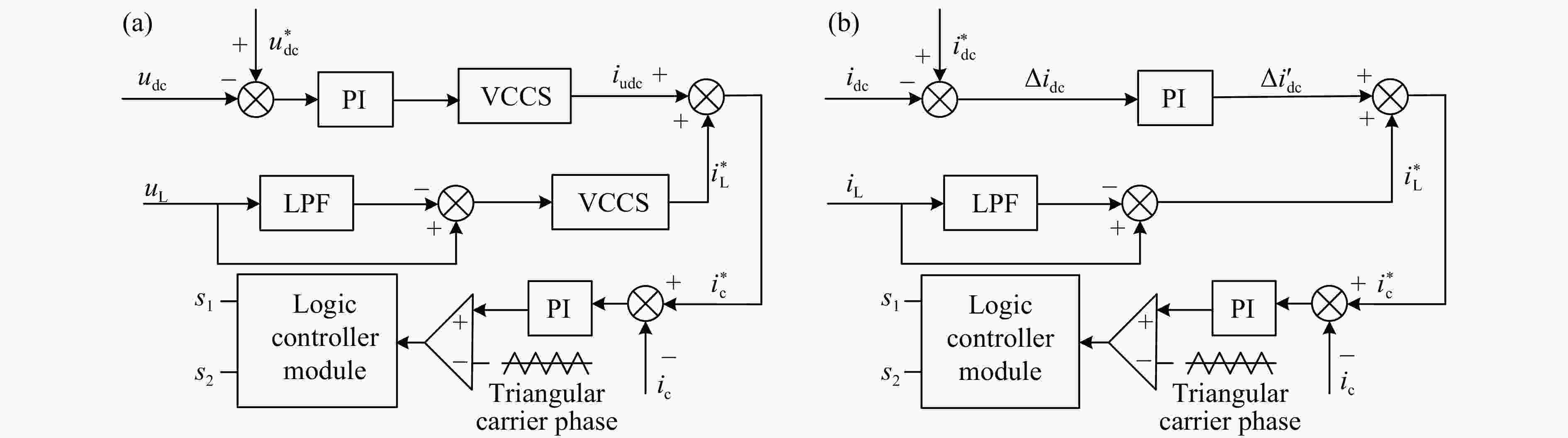
图5(a)和(b)分别给出了电压型和电流型有源电力滤波器的控制系统框图。VSAPF的控制系统是基于负载电压的前馈控制,控制系统调节器通过对检测到的负载纹波电压和直流侧储能电容的电压进行计算,产生脉冲宽度调制(Pulse Width Modulation,PWM)驱动信号,用于控制绝缘栅双极性晶体管(Insulated Gate Bipolar Transistor,IGBT)开关管的导通与关断;CSAPF控制系统基于负载电流的反馈,通过检测负载纹波电流和直流侧储能元件电感电流对CSAPF控制,对输出的纹波电流直接控制,提高CSAPF控制效率。
-
VSAPF的控制方式是通过纹波检测算法对检测到的负载电压
${{{u}}_{\rm{L}}}$ 提取出其中的纹波电压,利用纹波电压与纹波电流之间的转换关系,可得到${{i}}_{\rm{L}}^ * = - k* \left[ {u_{\rm{L}}} - \right. $ $ \left. LPF\left( {u}_{\rm{L}} \right) \right]$ ,其中k为电压电流转换系数,LPF为低通滤波器。此过程中VSAPF的控制近似为电压控制电流源(Voltage Controlled Current Source,VCCS),即${{i}}_{\rm{L}}^ * = k{u_{\rm{L}}}$ 。检测到的直流侧电压值${{{u}}_{\rm{dc}}}$ 和给定的直流侧电压参考值${{u}}_{\rm{dc}}^ * $ 做差比较,得到差值$\Delta {{u}}$ ,并对这个差值进行PI控制,获得指令电流${{{i}}_{\rm{udc}}}$ ,该值与纹波信号叠加,得到最终的纹波指令电流${{i}}_{\rm{c}}^ * = i_{\rm{L}}^ * + {i_{\rm{udc}}}$ 与VSAPF发出的补偿电流${{{i}}_{\rm{c}}}$ 相减,将差值$\Delta {{{i}}_{\rm{c}}}$ 送入载波调制器,进而得到调制信号波,控制VSAPF产生与电路中大小相等、方向相反的纹波电流,达到纹波抑制的目的。 -
CSAPF控制系统中需要提供恒定直流电流来抑制纹波电流。首先利用低通滤波器纹波检测算法检测纹波电流
${{i}}_{\rm{L}}^ * = - 1*\left[ {{{{i}}_{\rm{L}}} - LPF\left( {{i_{\rm{L}}}} \right)} \right]$ ,其次通过比较给定的电感电流参考值${{i}}_{\rm{dc}}^ * $ 与CSAPF直流侧储能元件电感电流实际值${{{i}}_{\rm{dc}}}$ ,得到差值信号$\Delta {{{i}}_{\rm{dc}}}$ ,对该差值进行PI控制,控制框图如图6所示。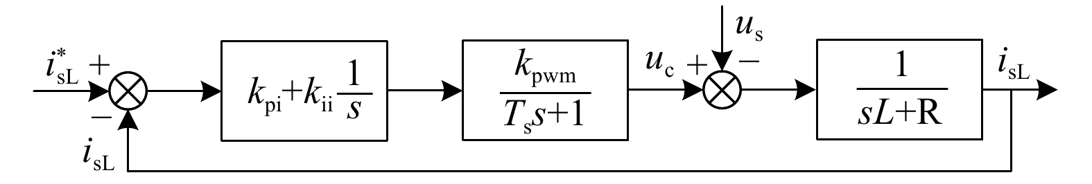
利用CSAPF的优点[15],设计电流环单环即可完成闭环控制系统设计,可得
式中:
${{{k}}_{\rm{pi}}}$ 为电流环PI控制器比例系数;${{{k}}_{\rm{ii}}}$ 为电流环PI控制器积分系数;${{{{{k}}_{\rm{pwm}}}} / {\left( {{T_{\rm{s}}}s + 1} \right)}}$ 表示PWM环节;${{{k}}_{\rm{pwm}}}$ 为PWM环节增益;${{{T}}_{\rm{s}}}$ 为控制周期。化简式(12)可得令
${{{{{k}}_{\rm{pi}}}} / {{k_{\rm{ii}}}}} = {{{L_{\rm{f}}}} / R}$ 以消除式(13)中零极点,可得根据式(14)可得电流环闭环传递函数:
由式(15)可以看出,电流环闭环传递函数为二阶系统,采用二阶系统最佳设计原则:
令式(15)等于式(16)可得:
式(17)中,取
$\xi {{ }} = 0.707$ ,则电流环PI控制器参数表达式为本文单相CSAPF中,电感
${L_{\rm{f}}} = 0.68\,{\rm{mH}}$ ,电阻${{R}} = 0.2\,\Omega $ ,控制周期${{{T}}_{\rm{s}}} = 100\,\mu {\rm{s}}$ ,PWM环节增益${{{k}}_{\rm{pwm}}} = 1$ ,可得电流环PI控制器参数为将式(19)分别带入到式(14)和(15)中,可以得到具体参数下电流环的开环传递函数表达式和闭环传递函数表达式:
依据式(20)得到电流环开环传递函数伯德图,如图7所示,零时对应幅频特性幅值频点为500 Hz,对应相角为93°。因此,设计的电流内环PI控制系统具有充裕的稳定裕度。

依据式(21)画出如图8所示的电流环闭环传递函数伯德图。观察图8,幅频特性中幅值为–3.6 dB时对应的频点为500 Hz,需要跟踪的反馈电流信号的频率为500 Hz,因此,设计的电流环PI控制系统可以准确的跟踪反馈电流信号。

本文设计的单相CSAPF系统的控制周期
${{{T}}_{\rm{s}}} = $ $ 100\,\mu {\rm{s}}$ ,在0 ~ 500 Hz频段内,电流环闭环传递函数可简化为根据式(22),系统可简化为一阶惯性环节,其延时
$200\,\mu {\rm{s}}$ 。因此,设计的电流内环PI控制系统在0 ~ 600 Hz频段内可以快速地跟踪反馈电流信号,为实现磁铁电源低频纹波的抑制提供了支撑。 -
利用MATLAB/Simulink软件分别对图1中的VSAPF和CSAPF完整系统进行仿真分析。为分析VSAPF和CSAPF对低频纹波的抑制性能,本文采用直流和交流叠加的纹波源,即选取直流分量50 A,交流部分选取频率分别为100/300/600 Hz,幅值大小为1/1.5/0.7 A的谐波,使用RL型(
$R\!=\!0.5\,\Omega,\;L\!=\!20\,\text{mH} )$ ,负载来检查VSAPF和CSAPF的系统性能。考虑到加速器直流稳定电源中开关器件的频率为10 kHz,设置有源电力滤波器中功率开关管的频率同为10 kHz。系统参数如表1所列。VSAPF CSAPF 名称 数值 名称 数值 滤波电感Lf 2 mH 滤波电感Lf 0.68 mH 滤波电容Cf 43 µF 直流侧电容Cdc 1.2 µF 直流侧电感Ldc 5 mH 直流侧电阻Rdc 1.3 Ω 直流侧电压${{u}}_{\rm{dc}}^ * $ 250 V 直流侧电流${{i}}_{\rm{dc}}^ * $ 9 A 负责侧电感Lload 2.3 mH 负载侧电感Lload 2.3 mH -
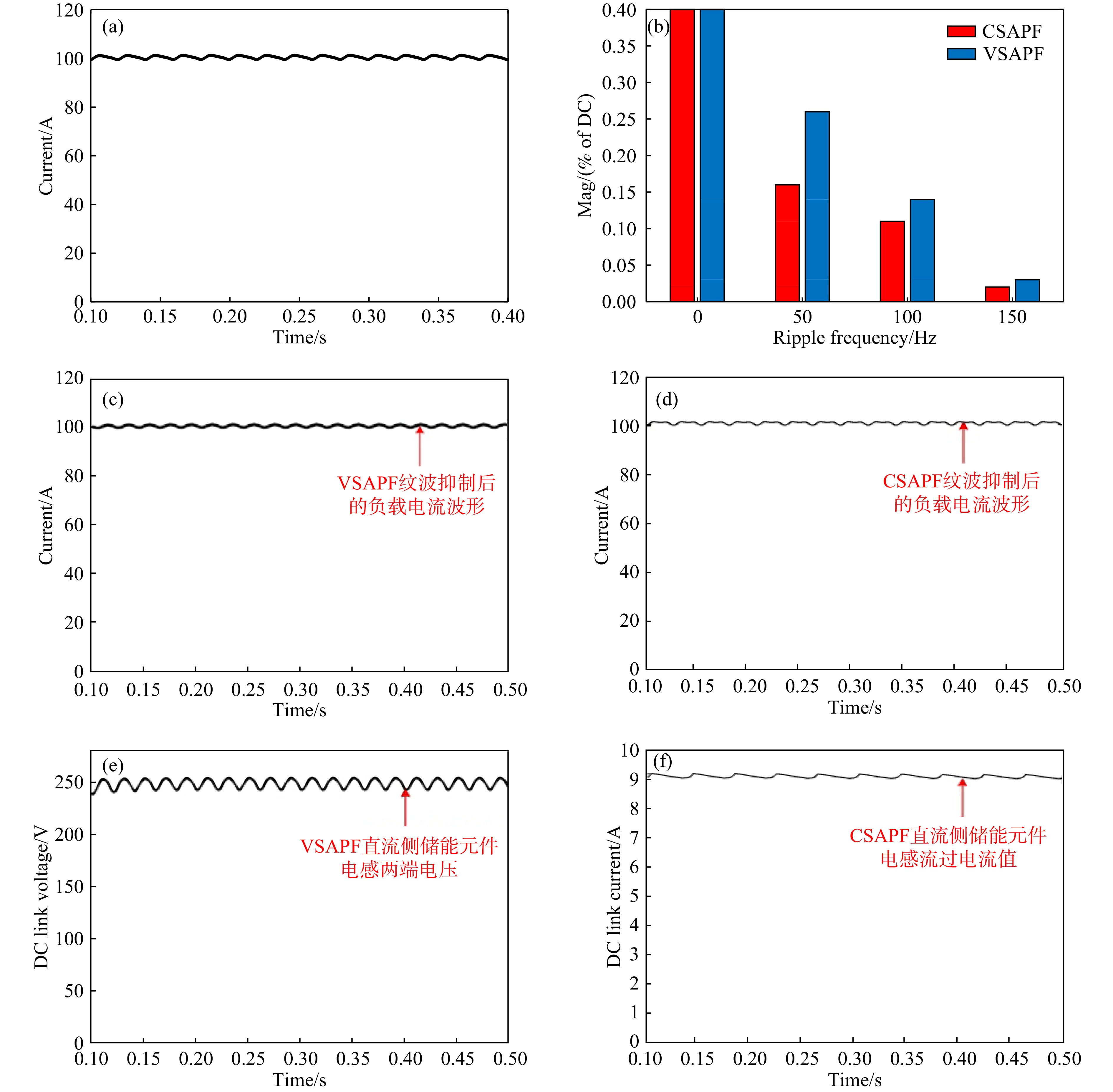
重离子加速器以磁铁负载为主,为准确测试VSAPF和CSAPF的性能,本文以RL型负载模拟磁铁负载。图9(a)为负载电流波形;图9(b)是对VSAPF和CSAPF抑制后的负载电流进行的快速傅里叶变换(Fast Fourier Transformation,FFT)分析;图9(c)为VSAPF抑制后的负载电流波形;图9(d)为CSAPF抑制后的负载电流波形;图9(e)是VSAPF直流侧储能元件电容两端电压;图9(f)是流过CSAPF直流侧储能元件电感的电流。纹波测量结果如图9(b)所示,VSAPF和CSAPF均能准确滤除纹波电流。

图9表明电流型有源电力滤波器对纹波的抑制效果略优于电压型有源电力滤波器,这种差异主要是由于所采用的控制策略。由于CSAPF能够对磁铁电源输出电流直接控制,相比VSAPF通过检测负载纹波电压,实现对磁铁电源输出电流的纹波抑制,可以更快速、更准确地对负载电流进行抑制。VSAPF和CSAPF分别对负载电流进行抑制,通过FFT分析,得到总谐波失真(Total Harmonic Distortion,THD)对比结果如图9(b)所示,VSAPF抑制后负载电流的THD为0.32%,CSAPF抑制后负载电流的THD为0.19%,THD相差0.13%。同时,图9(b)表明频率为50, 100 Hz的低频交流信号对负载电流的THD影响最大。
磁铁电源输出电流纹波抑制结果如图9(c)和(d)所示,考虑包括开关电流纹波在内的THD,CSAPF(如图9d)的THD比VSAPF(如图9(c))的THD值更低。图9(e)和(f)分别是VSAPF和CSAPF直流侧储能元件的电压和电流值。为消除有源电力滤波器等电力电子设备自身产生的谐波,需要在12脉冲电路和有源电力滤波器之间设置滤波器,考虑到
${{{u}}_{\rm{dc}}}$ 和${{{i}}_{\rm{dc}}}$ 各自的特性,CSAPF采用二阶LC滤波器,比使用一阶L滤波器的VSAPF更有效地消除设备自身带来的谐波。 -
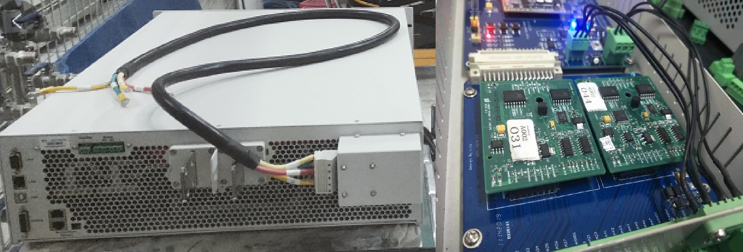
对上述CSAPF控制系统在实验平台上进行原理验证。为验证本文所提方案的正确性,搭建CSAPF实验平台,初步测试了纹波抑制效果,实验设备如图10所示。直流电源参数为:电源输出电流为50 A,电压为2.5 V。负载选用中心孔径80 mm,铁芯长度为160 mm,磁场梯度为8 T/m的四极透镜。CSAPF直流侧储能电感为5 mH,二阶滤波器LC的具体数值分别为0.68 mH、43
$\mu {\rm{F}}$ 。
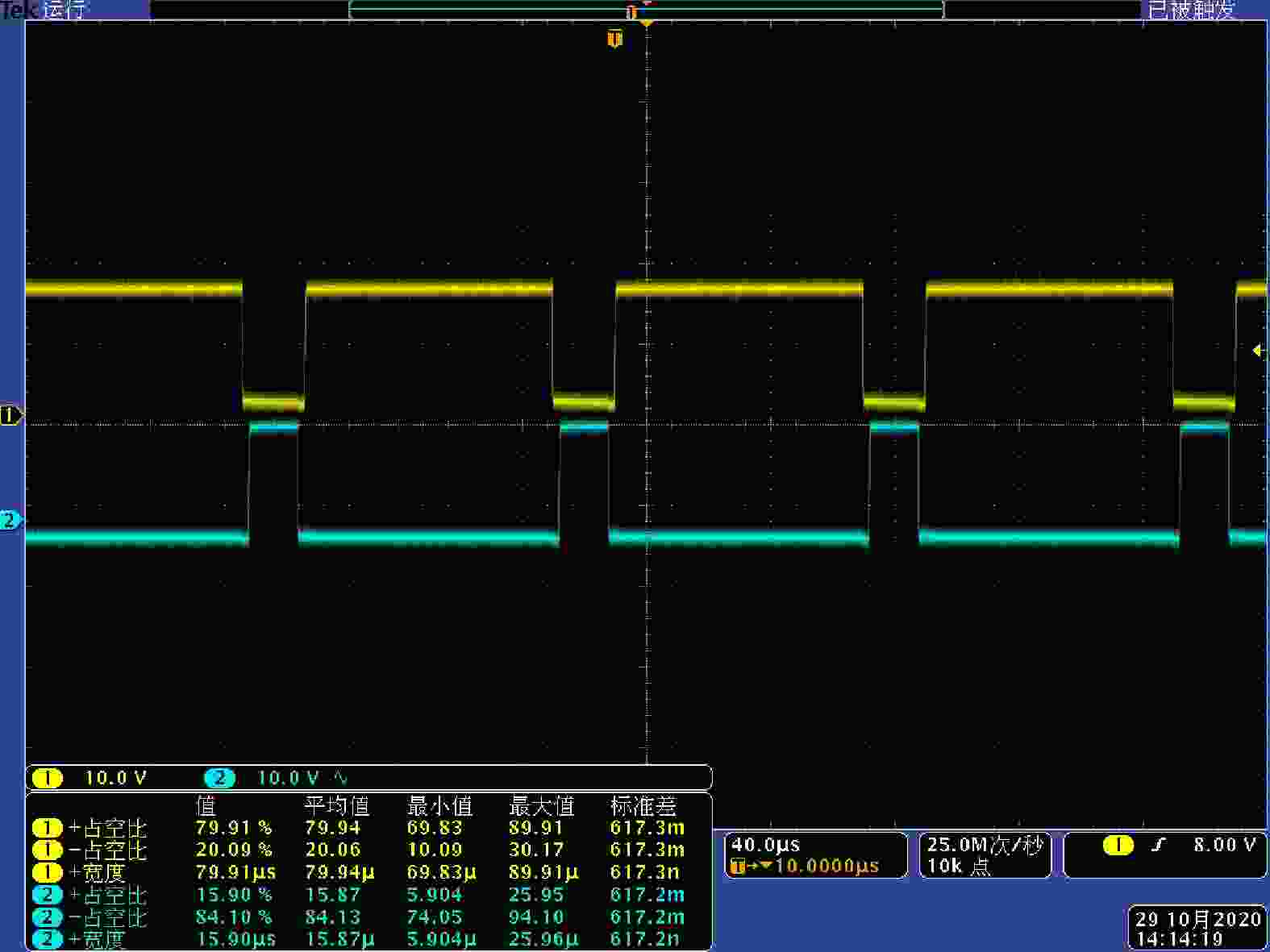
给待测试的主回路通电,通过PC界面控制CSAPF系统开机,使CSAPF系统处于开环状态,在PC上位操作界面上通过写入直流给定使得CSAPF能够输出一个较小的电流,进而检查各传感器的信号是否准确;ADC转换、DAC转换采样的结果是否正常;PWM信号是否正常;各驱动信号是否正常。图11是利用示波器测试开环状态下PWM驱动信号,PWM模块产生了理想状态下两路脉冲信号按照理论值正常工作,用于控制IGBT的导通与关断。
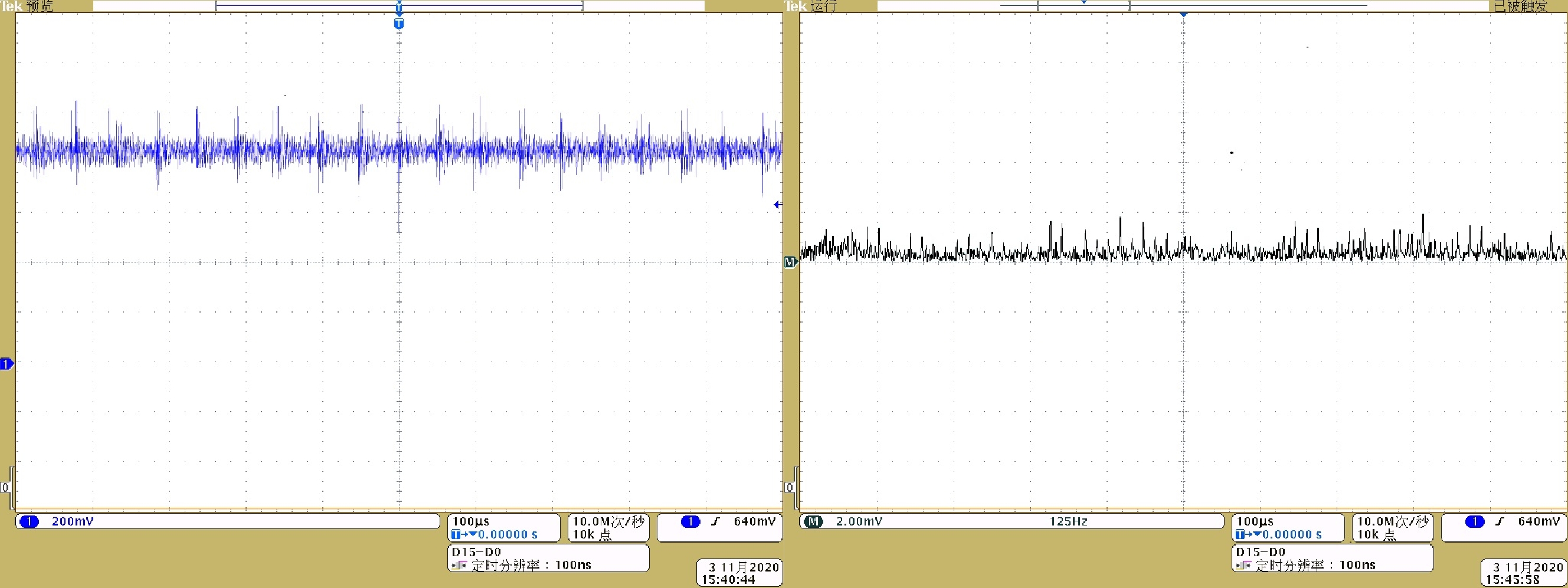
CSAPF未投入使用时负载电流波形及快速傅里叶变换频谱分析结果见图12。结果显示,利用高精度零磁通电流传感器检测的负载电流纹波主要为100/300/600 Hz等低频纹波信号,计算得到电流纹波系数为
$2.5 \times {10^{{{ - }}5}}$ 。图13为CSAPF投入后的负载电流纹波波形及FFT分析,通过对比图12与图13,可以发现在CSAPF投入后,负载电流纹波显著减小,电流纹波系数为$1.6 \times {10^{{{ - }}5}}$ 。验证了CSAPF对负载电流纹波可以更快速、更准确地进行抑制。

-
本文对电压型和电流型有源电力滤波器进行了比较。从调制方法、主电路拓扑结构和控制系统三个方面,对两种系统在加速器磁铁电源纹波抑制中的运行性能进行了仿真验证。结果表明,两种有源滤波器都能对纹波电流有效抑制,负载电流的纹波电流系数低于
${10^{{{ - }}5}}$ ,THD降低到0.5%以下。CSAPF通过简单的直接电流控制,实现纹波电流的抑制,但直流侧大电感的体积、保持导通带来的额外电能损耗限制了CSAPF的大范围应用;VSAPF采用双闭环控制,滤波器开关纹波较大,增加了纹波抑制的难度。综上所述,虽然VSAPF是当前主要研究方向,但本文的研究结果表明,CSAPF也为纹波抑制提供了很好的选择,尤其在以电流为主要研究目标的重离子加速器等大科学装置中,CSAPF对纹波电流的控制更准确,抑制效率更高。
Research on Ripple Suppression of Magnet Power Supply Based on CSAPF
doi: 10.11804/NuclPhysRev.38.2020064
Funds:
National Naturl Science Foundation of China(11405239); Openness Foundation of State Key Laboratory of Large Electric Drive System and Equipment Technology(SKLL-DJ052016011)
- Received Date: 2020-08-18
- Rev Recd Date: 2021-04-07
- Available Online: 2021-07-22
- Publish Date: 2021-06-20
-
Key words:
- ripple suppression /
- compensation accuracy /
- main circuit topology /
- active power filter
Abstract: Due to the existence of a large number of nonlinear devices in the accelerator system, a large number of ripples are generated, which seriously affects the control of the accelerator magnetic field on the particle trajectory. In order to realize the suppression of accelerator DC power supply ripple, related researches mainly focused on using voltage-type active power filter to reduce DC power supply ripple, but this method has problems such as insufficient suppression accuracy, response delay, and large switchgear loss. In view of the above problems, this paper compares the main circuit topology of current-type and voltage-type active power filters, investigates the pulse width modulation technology and control strategies of current-type and voltage-type active power filters, and analyzes the performance of different active power filters in the accelerator system to suppress the output current ripple of magnet power supply. Through simulation analysis and experimental verification, it is found that the current-type active power filter has a significant suppression effect on the output current ripple of the magnet power supply, and the current-type active power filter can directly control the output ripple current, and the ripple accuracy is suppressed more highly. With the CSAPF put into use, the load current ripple is significantly reduced, and the current ripple coefficient reaches 1.6×10⁻⁵.
| Citation: | Yongqiang WANG, Xinhua YANG, Jiqiang LI, Yuzheng HUANG, Daqing GAO, Wei LUO. Research on Ripple Suppression of Magnet Power Supply Based on CSAPF[J]. Nuclear Physics Review, 2021, 38(2): 166-174. doi: 10.11804/NuclPhysRev.38.2020064

|


 甘公网安备 62010202000723号
 DownLoad: