


-
Heavy ion collision has been the almost unique method to study properties of dense nuclear matter in the laboratory[1-5]. The Cooler-Storage-Ring(CSR) External-target Experiment(CEE)[6], which is being constructed since 2020, will be the first large-scale experiment in high-energy nuclear physics built in China covering the GeV energy region. In the future, it can also be used at the High Intensity heavy ion Accelerator Facility(HIAF)[7], which is now under construction. Experimental studies utilizing CEE aim at many physical goals including the phase structure of QCD matter in high baryon density region, as well as the equation of states of nuclear matter at super-saturation densities. CEE includes a micro-pixel beam monitor, a large volume Time Projection Chamber(TPC), a Multi-Wire Drift Chamber(MWDC) array, Time-of-Flight detectors(TOF) and a large acceptance super-conducting dipole magnet.
TPC’s[8] are widely used in high energy and nuclear experiments. The CEE TPC has a sensitive volume of about 1
$ {\rm m}^{3} $ , which will be the largest TPC ever constructed and used in China. It can provide track information, including 3-dimensional position, momentum, charge and energy loss, for charged particles, which is crucial for almost all physics analyses that will be conducted at CEE in the future. Thus the TPC is the most important detector for CEE. Fig. 1 shows a schematic plot of the CEE TPC. It has a sensitive volume filled with gas, where uniform electrical and magnet fields are applied in the vertical direction. When a charged particle goes through the sensitive volume, the curvature of its trajectory in the magnet field can be used to obtain its charge and momentum. Electrons created via the ionization process along the charged particle trajectory would drift in the electrical field towards 4 layers of large area standard Gas Electron Multiplier(GEM) foil[9] at the top of the TPC, where electron avalanche will happen to amplify the signal by a factor of about one thousand. A plane of read-out pads is positioned above the GEM layers. The read-out pads are directly connected to SAMPA read-out electronics chips[10]. Each SAMPA chip integrates 32 channels of charge sensitive amplifiers, semi-Gaussian shapers and 10-bit Analog-to-Digital Converters(ADC). The state-of-the-art SAMPA chips make CEE TPC capable of reading out data at an event rate of 10 kHz. And the usage of the GEM technology instead of traditional anode wires minimizes space charge caused by positively charged ions from avalanche drifting back to the sensitive volume, which would destroy the uniformity of the electrical field. 3-dimensional information of the ionization position can be reconstructed from the signals recorded by the read-out pads. Ionization position in the drift direction (drift distance) can be calculated by measured drift time and drift velocity, while the ionization position in the rest 2 dimensions can be reconstructed from the position of fired pads. Eventually, three-dimensional trajectories of charged particles can be reconstructed. Heavy ion collisions at CEE can create up to 200 charged particles. It is a great challenge to reconstruct the trajectories of so many charged particles with required efficiency ($>90\%$ ) and momentum resolution ($<5\%$ ).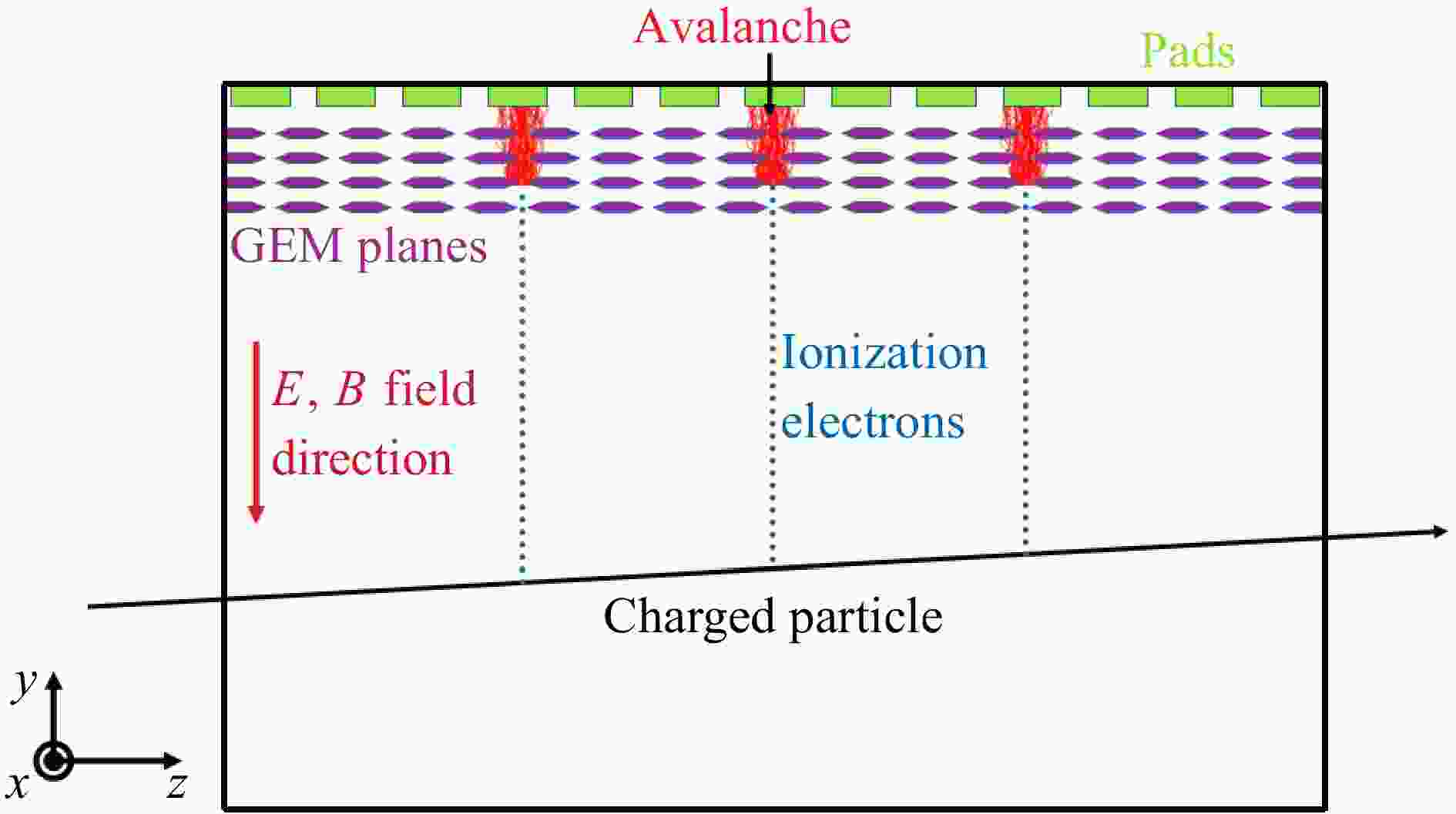
Figure 1. (color online)Schematic plot of CEE TPC.
The design and key technologies of the CEE TPC is being developed. For now, a basic version of TPC design is used for this study. The sensitive volume of TPC is a box of 120 cm×80 cm×90 cm along
$ x, y $ and$ z $ directions respectively, where$ z $ is the beam line direction and$ y $ is parallel to the drift electrical field and magnetic field, as shown in Fig. 1. The read-out plane is divided along$ z $ direction into 75 pad rows. Each pad row consists of 240 pads with the size of 5 mm ($ x $ )×12 mm ($ z $ ). Working gas of the TPC is Ar 90%+CH$ _{4} $ 10% at the pressure of 1 atm. With drift electrical field strength of 130 V/cm, the electron drift velocity is 5.5 cm/µs. We use SAMPA in a mode with the read-out frequency of 10 MHz. The corresponding drift length per time bin is 0.55 cm. The 80 cm drift length thus corresponds to about 145 time bins.To reconstruct the trajectory of a charged particle, the first step is to group together signals at neighboring pads and time bins in the same pad row, into a so-called cluster. Usually, one cluster corresponds to the signals that a particle creates when it goes through a
$ x $ -$ y $ gas layer that projects to a pad row, called a hit. When the particles are very dense in space, hits from different particles may also create signals adjacent to each other. In this case, one cluster may contain more than one hit. It is important to be able separate hits from different particles in the same cluster, in order to have good double-track separation ability and track reconstruction efficiency. In the following sections of this paper, the cluster reconstruction algorithm for the CEE TPC, as well as some results from it will be reported. The CEE TPC cluster construction software has been made taking the cluster reconstruction software for the NICA-MPD experiment[11] as reference. It is a part of the CeeRoot package, which is being developed based on the FairRoot package[12]. The output hits of cluster reconstruction can later be connected to form tracks. The software for track reconstruction is being developed. The current TPC design will be further optimized in the future once the track reconstruction software is available.The read-out signals used in this study are generated by Monte-Carlo(MC) simulation. The particle transportation and energy loss in the TPC sensitive volume is simulated using the GEANT package[13]. Then ionization is simulated by randomly generating electrons along the particle trajectory. Next, drift and diffusion of these electrons in the sensitive volume, as well as electron avalanche in the GEM layers, are simulated according to parameters extracted from a simulation study using the GarField++[14] software. Signals are then distributed on read-out pads according to avalanche positions, spreads and magnitudes. Finally, the SAMPA chip electronics responses are simulated, using measured Quasi-Gaussian response signal shape and noise level. The output read-out signals are ADC values at different pad rows, pad numbers and time bins. Complicated effects such as nonuniform electrical and magnetic fields, space charge due to positively charged ions in the sensitive volume, and cross-talk between different read-out channels, are not considered in the current simulation.
-
The CEE TPC cluster reconstruction consists of three steps: finding 2-dimensional(2D) clusters, finding peaks in clusters, and creating hits. These will be described in this section.
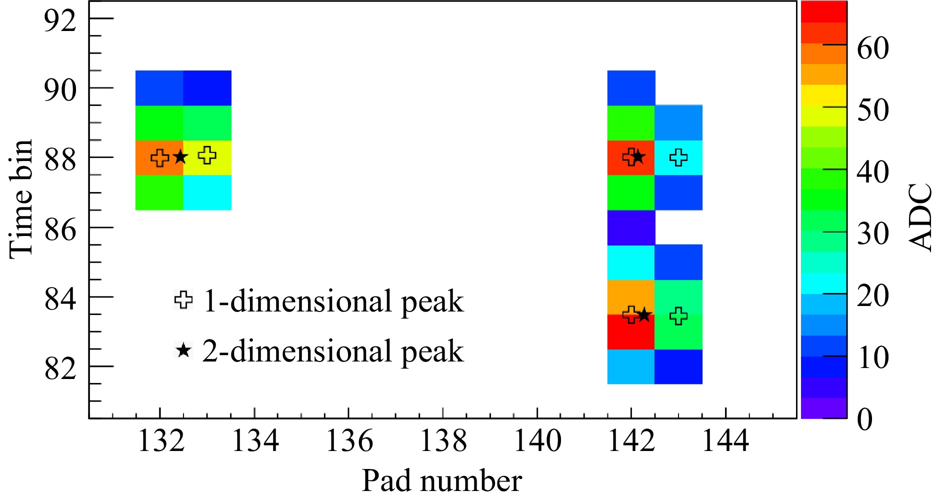
First, neighboring signals in the same pad row are grouped together to form a 2D cluster. Fig. 2 shows 2 example 2D clusters created by 0.5 GeV/
$ c $ protons traveling through the TPC. For each pad row, the plane of pad number vs. time bin is scanned for signals. When a signal is found (e.g., pad number 132, time bin 87 in Fig. 2), the neighboring 8 positions from current pad number$ -1 $ to current pad number$ +1 $ , from current time bin$ - 1 $ to current time bin$ + 1 $ , will be searched immediately for more signals. The above step will be iterated on newly found signals ($ e.g. $ , pad number 132, time bin 88 in Fig. 2), until all neighboring signals are found. Then all these found signals is grouped together to form a 2D cluster. In this way the whole pad number vs. time bin plane is scanned.
Figure 2. (color online)Example 2D clusters with a single peak(left) and 2 up-and-down peaks(right).
The second step of cluster reconstruction is finding peaks in each found cluster. A typical 1-hit cluster, created by one charged particle, should have the maximum ADC at the center of the cluster and lower ADC values at surrounding positions, as shown in Fig. 2(left cluster). On the other hand, multi-hit clusters should have multi-peak structures in terms of ADC values, as shown in Fig. 2(right cluster). Being able to identify multi-peaks within a cluster can improve 2-track separation ability for CEE TPC, which is crucial in the high multiplicity environment in heavy ion collisions. First, 1-dimensional (1D) peaks are found in time bin (
$ y $ ) direction for each pad number in the cluster. As shown in Fig. 2, the ADC values at pad number 142 forms a peak-valley-peak structure. When the ratio of the first peak’s maximum ADC value over the minimum ADC in the valley is above a certain threshold (2 for now), two peaks are identified. This threshold of the ratio can help avoid splitting wrongly one hit into two hits due to ADC fluctuations at the top of a peak. Right now, only the first peak is compared with the valley for the simplicity of the code. In the future, the algorithm can be further optimized so that both peaks are compared with the valley. The signal with the minimum ADC ($ e.g. $ , time bin 86 at pad number 142) is the boundary between the adjacent peaks. As shown in the Fig. 3(right), time bin$ 82\sim86 $ form the first peak; time bin$ 87\sim90 $ form the second peak. The 1D peak$ y $ position is calculated from the drift velocity and ADC weighted average time bin number of signals in the peak, as marked by the open crosses in Fig. 2. The 1D peak ADC is calculated as the total ADC of all signals in the peak. After 1D peak finding in the time bin ($ y $ ) direction is done for all pad numbers in the cluster, peaks are then combined along the pad number ($ x $ ) direction. 1D Peaks at neighboring pads within 2 cm in$ y $ direction are combined into a 2D peak. The x position of the 2D peak is calculated from the ADC weighted pad number. The final reconstructed 2D peaks are marked by solid star markers in Fig. 2.
Figure 3. (color online)ADC signal vs. time bin in the pad number 132(left) and 142(right).
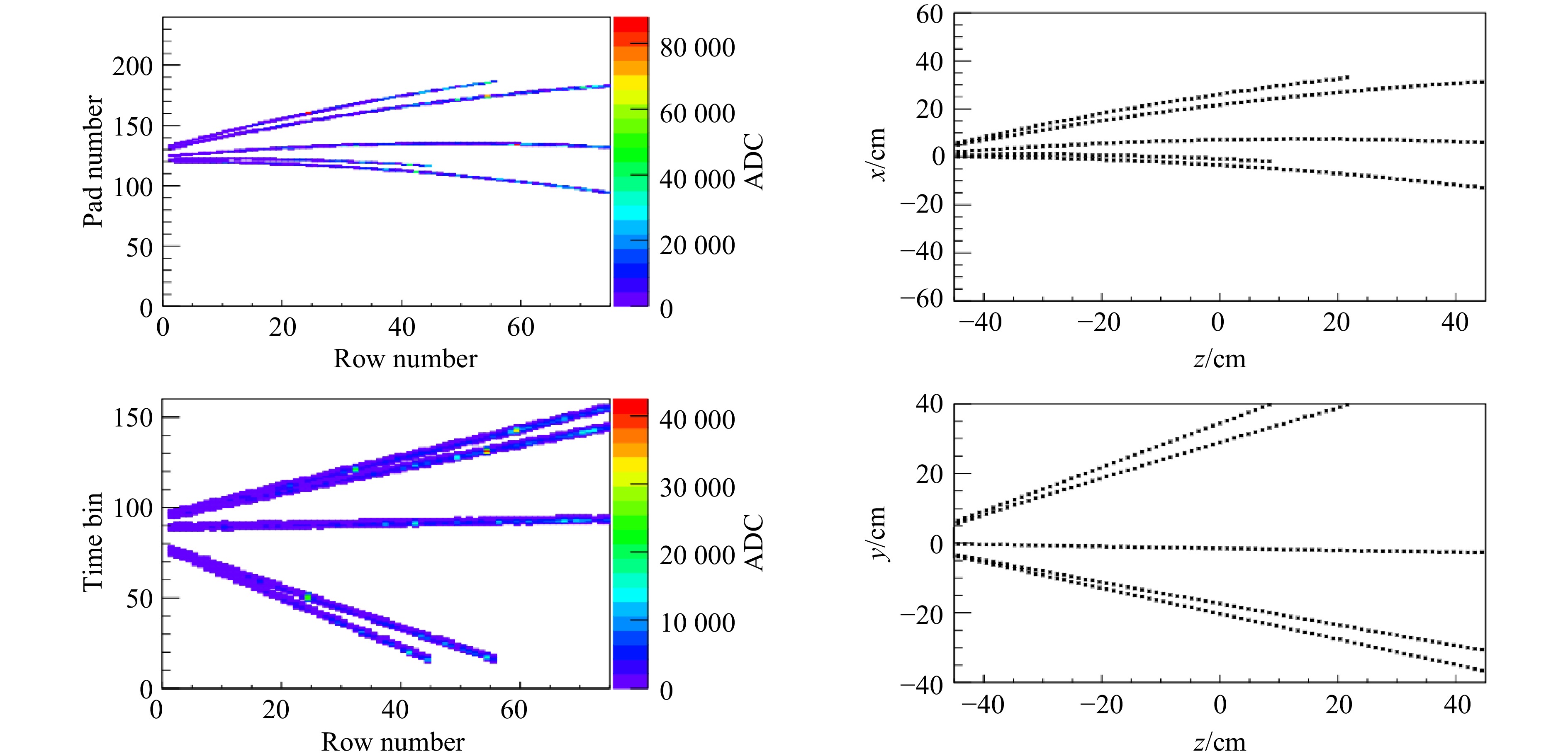
Finally, hits are created from 2D peaks in clusters. The ADC weighted position
$ x $ and$ y $ of the 2D peak are assigned as the hit position$ x $ and$ y $ respectively. The hit position$ z $ is the center$ z $ of the pad row. The hit energy loss, which is useful for particle identification, is proportional to the 2D peak total ADC. For real data hits, various corrections on the hit position will be applied due to space charge, non-uniform magnetic field and non-uniform drift electrical field. Fig. 4 shows the simulated signals and reconstructed hits for one example event. Since the read-out pads are placed at the top of the TPC, the upper electrons will arrive earlier. This makes the simulated signals inverted in the$ y $ direction as in Fig. 4(bottom left).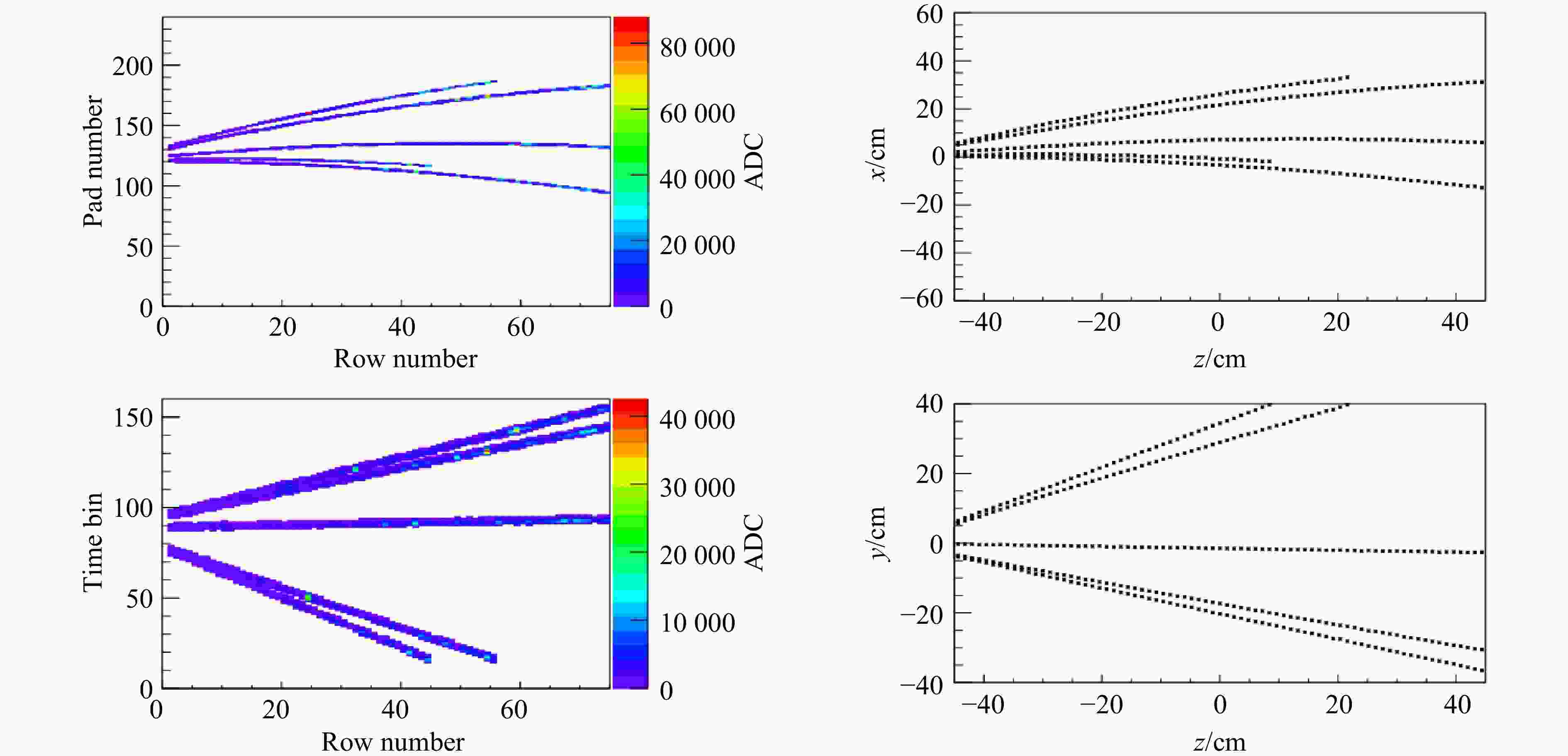
Figure 4. (color online)Simulated signals and reconstructed hits for one example event with
$xz$ (top) and$yz$ (bottom) view. -
To test the cluster reconstruction algorithm, we simulated 0.5 GeV/
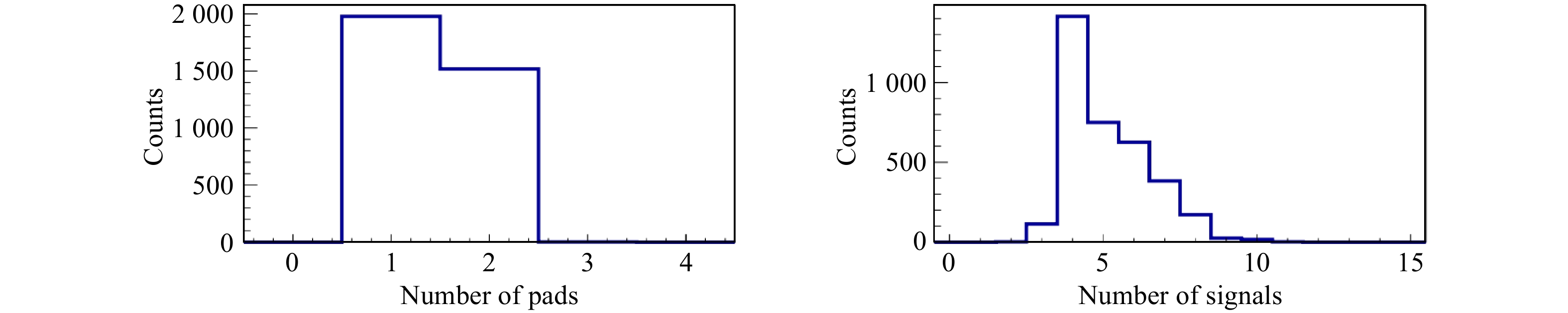
$ c $ protons traveling through the TPC in this article. The protons generated by MC are distributed at various$ x $ and$ y $ positions in order to have an average evaluation of the performance. This is because longer drift length leads to larger electron diffusion effect, and the particle positions at the middle or edge of a pad or time bin may also lead to slightly different performance.Fig. 5 shows the results of number of pads and number of signals for reconstructed hits with simulated protons traveling along
$ z $ direction. We can see that there are$ 1\sim2 $ fired pads for each hit, while the number of signals is around 5 on average. This is caused by the width of the semi-Gaussian signals from the SAMPA electronics chips.
Figure 5. (color online)Distributions of number of pads(left) and number of signals(right) for reconstructed hits with simulated protons traveling through the TPC along the
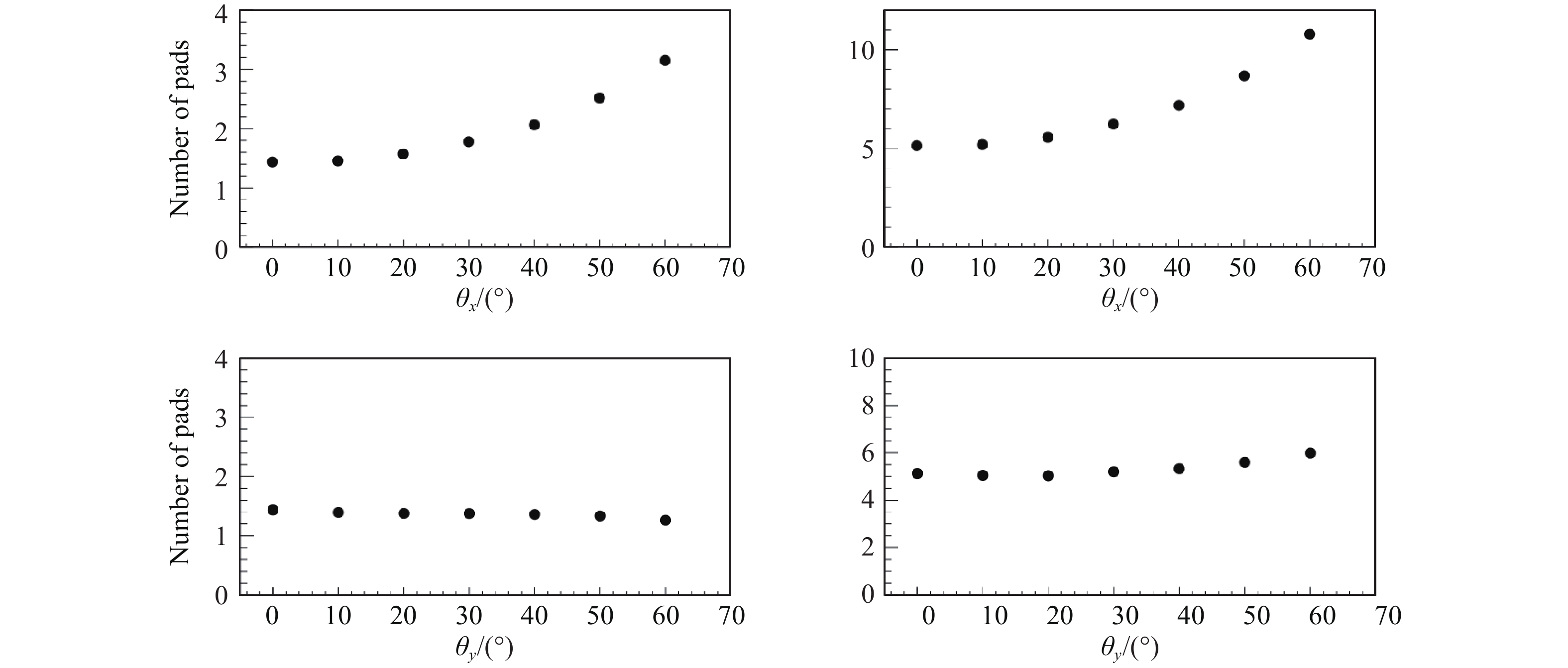
$z$ direction.Fig. 6 shows the average number of pads and average number of signals of the hits, when the protons have an angle relative to the
$ z $ direction. Here$ \theta_{x} $ ($ \theta_{y} $ ) is the angle between the track direction and the$ z $ axis in the$ xz(yz) $ plane. We can see from the top 2 panels that the average numbers of fired pads and signals both increase with increasing$ \theta_{x}. $ Average number of fired pads is almost a constant as a function$ \theta_{y} ,$ while average number of signals increase slightly with increasing$ \theta_{y} $ , as shown in the bottom 2 panels of Fig. 6.
Figure 6. Average number of pads(left) and average number of signals(right) vs. particle angle
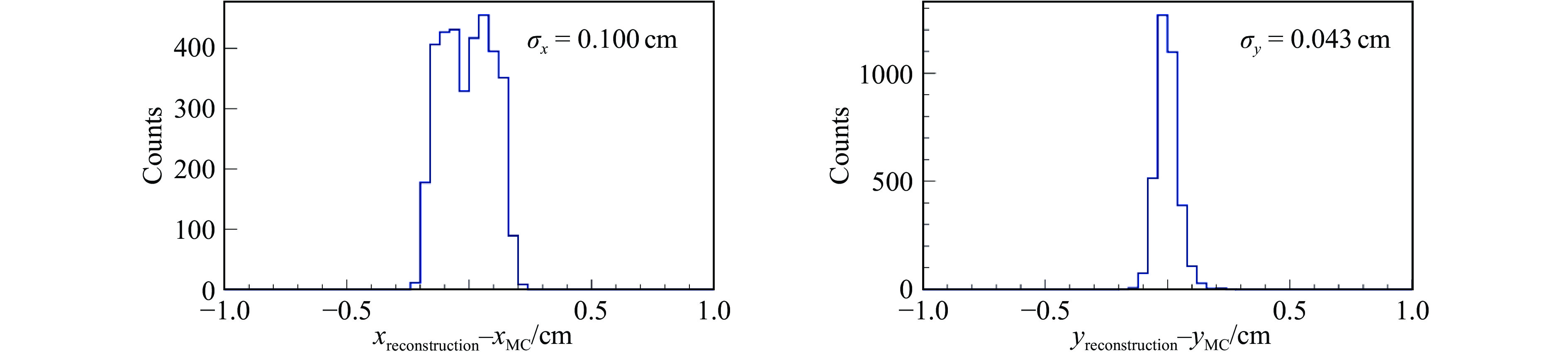
$\theta_{x}$ (top) and$\theta_{y}$ (bottom).Fig. 7 shows the distributions of differences between the reconstructed hit positions and corresponding MC point positions in the
$ x $ (left) and$ y $ (right) directions, when protons with the momentum of 0.5 GeV/$ c $ go through the TPC volume along the$ z $ direction. The result root mean square position resolutions$ \sigma_{x} $ and$ \sigma_{y} $ are 0.100 and 0.043 cm, respectively. These resolutions are caused by finite pad width and time bin length, diffusion of drift electrons, diffusion of avalanche electrons, electronics noise and so on. In$ x $ direction, the pad width is the dominant contribution of the hit resolution. When only one pad is fired, no matter where the track goes through the 0.5 cm pad width, the pad center will be recorded as the hit position. Thus a flat top structure can be seen in the distribution in Fig. 7(left). In$ y $ direction, since SAMPA will always produce a signal with about 5 time bins, the ADC-weighted average time bin is used to calculate the hit$ y $ . Thus the distribution in Fig. 7(right) has a Gaussian shape.
Figure 7. (color online)Distributions of differences between the reconstructed hit positions and corresponding MC point positions in the
$x$ (left) and$y$ (right) directions.When a particle has an angle with respect to the
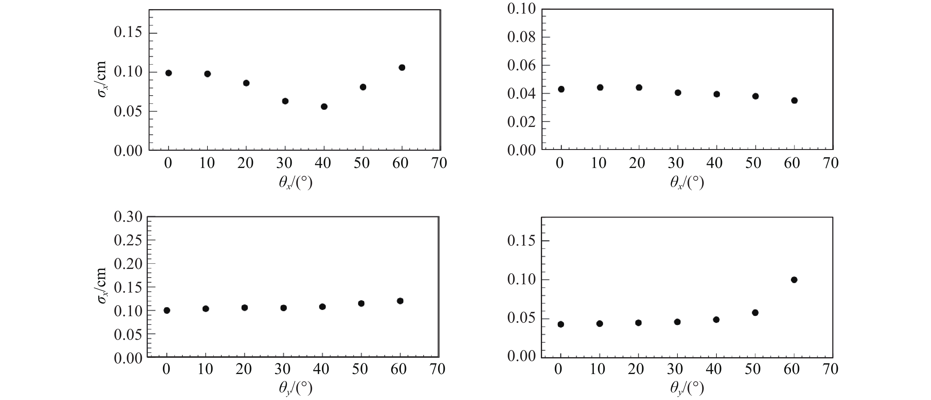
$ z $ direction, in other words, not perpendicular to the gas layer corresponding to a pad row, the hit position resolution will change because the track fires more pads and/or time bins, making the cluster wider in$ x $ and/or$ y $ directions. Fig. 8 shows hit position resolutions$ \sigma_{x} $ ,$ \sigma_{y} $ vs. particle angles$ \theta_{x} $ and$ \theta_{y} $ . When$ \theta_{x} $ increases from 0 to 40 degrees,$ \sigma_{x} $ decreases. This is because at 0 degree, a lot of hits are from single-pad clusters, and there is no information about where the track goes through the 0.5 cm pad width. When$ \theta_{x} $ increases, more than one pad may be fired, the ADC weighted pad number provides more information about the hit position than the single-pad case. However, when$ \theta_{x} $ ($ \theta_{y} $ ) increases from 40 (0) degrees,$ \sigma_{x} $ ($ \sigma_{y} $ ) increases, because the cluster becomes even wider in$ x (y) $ direction. On the other hand$ \sigma_{y} $ ($ \sigma_{x} $ ) is almost constant as a function of$ \theta_{y} $ ($ \theta_{x} $ ). This result gives some hint about the relative contributions of the 0.5 cm pad width and other effects to the hit resolution, which will be helpful for the read-out pad design optimization in the future.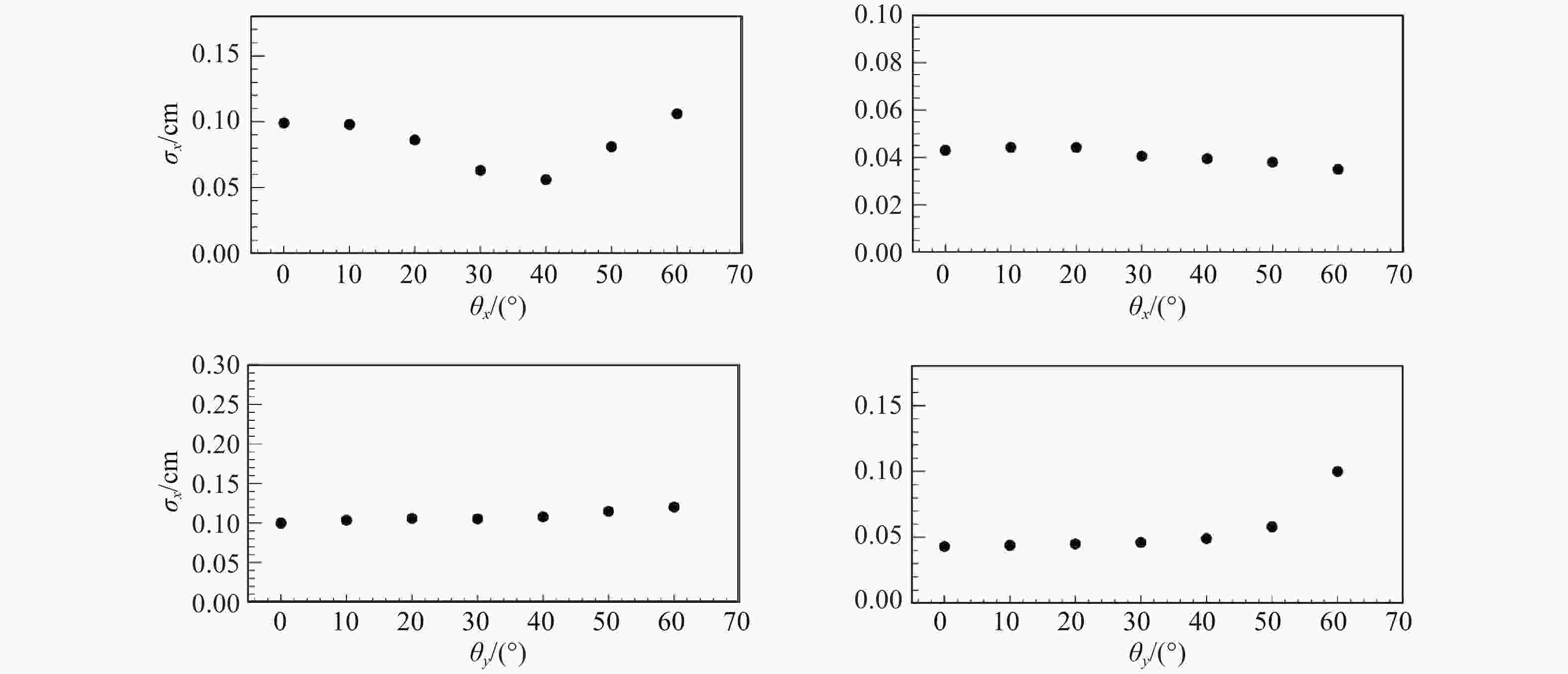
Figure 8. Hit position resolutions
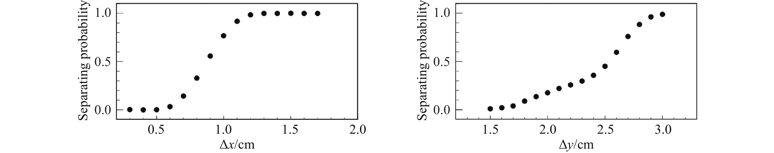
$\sigma_{x}$ (left),$\sigma_{y}$ (right) vs. particle angles$\theta_{x}$ (top) and$\theta_{y}$ (bottom).Besides position resolution, another key performance characteristic of CEE TPC and the cluster finding algorithm is double-track resolution. With high multiplicity in heavy ion collisions, it’s important for CEE TPC to be able to separate hits from 2 nearby particles, in order to achieve high track reconstruction efficiency. Fig. 9 shows double-track separating probability vs. distances between two 0.5 GeV/
$ c $ protons in the$ x $ (left) and$ y $ (right) directions. This is evaluated by simulating 2 protons parallel to each other along$ z $ direction, with a certain distance in$ x $ or$ y $ direction. The double-track separating probability is defined as the fraction of cases where 2 separate hits are reconstructed for the 2 simulated protons. We can see that 90% of double-track separating probability is achieved for distances of 1.1 cm and 2.8 cm in$ x $ and$ y $ direction, respectively. The double-track resolution of 2.8 cm in$ y $ direction is comparable with 5 time bins, the typical signal width of the SAMPA chip. Thus, the algorithm to separate peaks in a cluster using ADC patterns described in section 2 does improve double-track resolution.
Figure 9. Double-track separating probability vs. distances between two protons in the
$x$ (left) and$y$ (right) directions. -
In summary, we developed a cluster reconstruction algorithm for the CEE TPC. 2D clusters are reconstructed by iterating searching for neighboring signals in the time bin vs. pad number plane. The ADC patterns are used to identify multiple peaks within a cluster, in order to separate nearby hits in high multiplicity environment of heavy ion collisions. For particles perpendicular to the gas layer corresponding to a pad row, 0.100/0.043 cm of hit resolution and 1.1/2.8 cm of double-track resolution (with 90% separation probability) are achieved in the
$ x / y $ direction. This work has laid foundation for the development of track reconstruction software for the CEE TPC. It will also be used for the optimization of CEE TPC pad design in the future.
Cluster Reconstruction for the CSR External-target Experiment (CEE) Time Projection Chamber
doi: 10.11804/NuclPhysRev.38.2021021
Funds:
National Natural Science Foundation of China(11927901)
- Received Date: 2021-03-11
- Rev Recd Date: 2021-04-22
- Publish Date: 2021-12-20
-
Key words:
- CSR External-target Experiment(CEE) /
- Time Projection Chamber(TPC) /
- cluster reconstruction
Abstract: The Cooler-Storage-Ring External-target Experiment(CEE) is a spectrometer to study the properties of nuclear matter at high baryon density region. The CEE time projection chamber, which uses the state-of-the-art SAMPA electronics read-out chips is the key sub-detector of CEE. Neighboring signals in the same pad row are first grouped together to form a 2-dimensional cluster. Then a hit is created for each cluster at the ADC weighted average signal position. A cluster may also be divided into two or more hits, when the signal ADC vs. time bin has a peak-valley-peak structure, in order to obtain better two-track separation ability. The performance of the algorithm, including 0.100/0.043 cm of hit resolution and 1.1/2.8 cm of double-track resolution in the
| Citation: | Yi ZHU, Kumar Shyam, Chenlu HU, Zixuan CHEN, Yapeng ZHANG, Fengyi ZHAO, Xianglun WEI, Limin DUAN, Nu XU, Hao QIU. Cluster Reconstruction for the CSR External-target Experiment (CEE) Time Projection Chamber[J]. Nuclear Physics Review, 2021, 38(4): 416-422. doi: 10.11804/NuclPhysRev.38.2021021

|


 甘公网安备 62010202000723号
 DownLoad: